
Inside the Forging Workshop
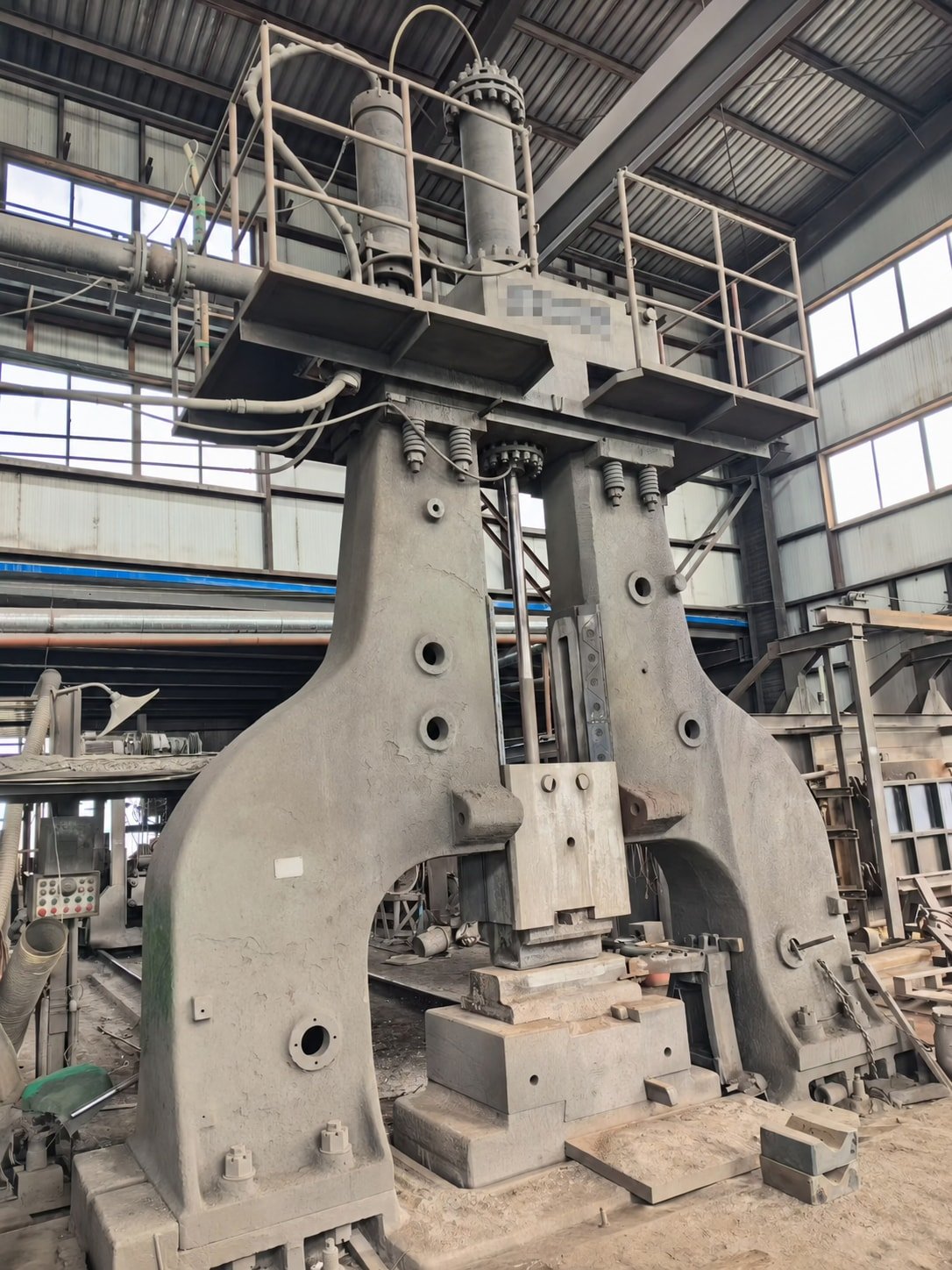
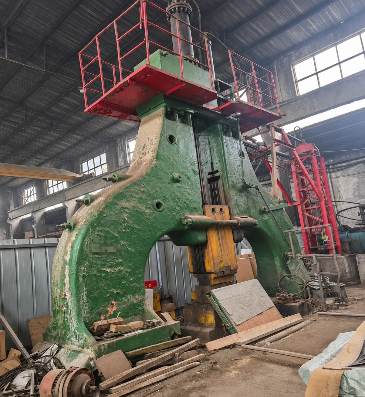
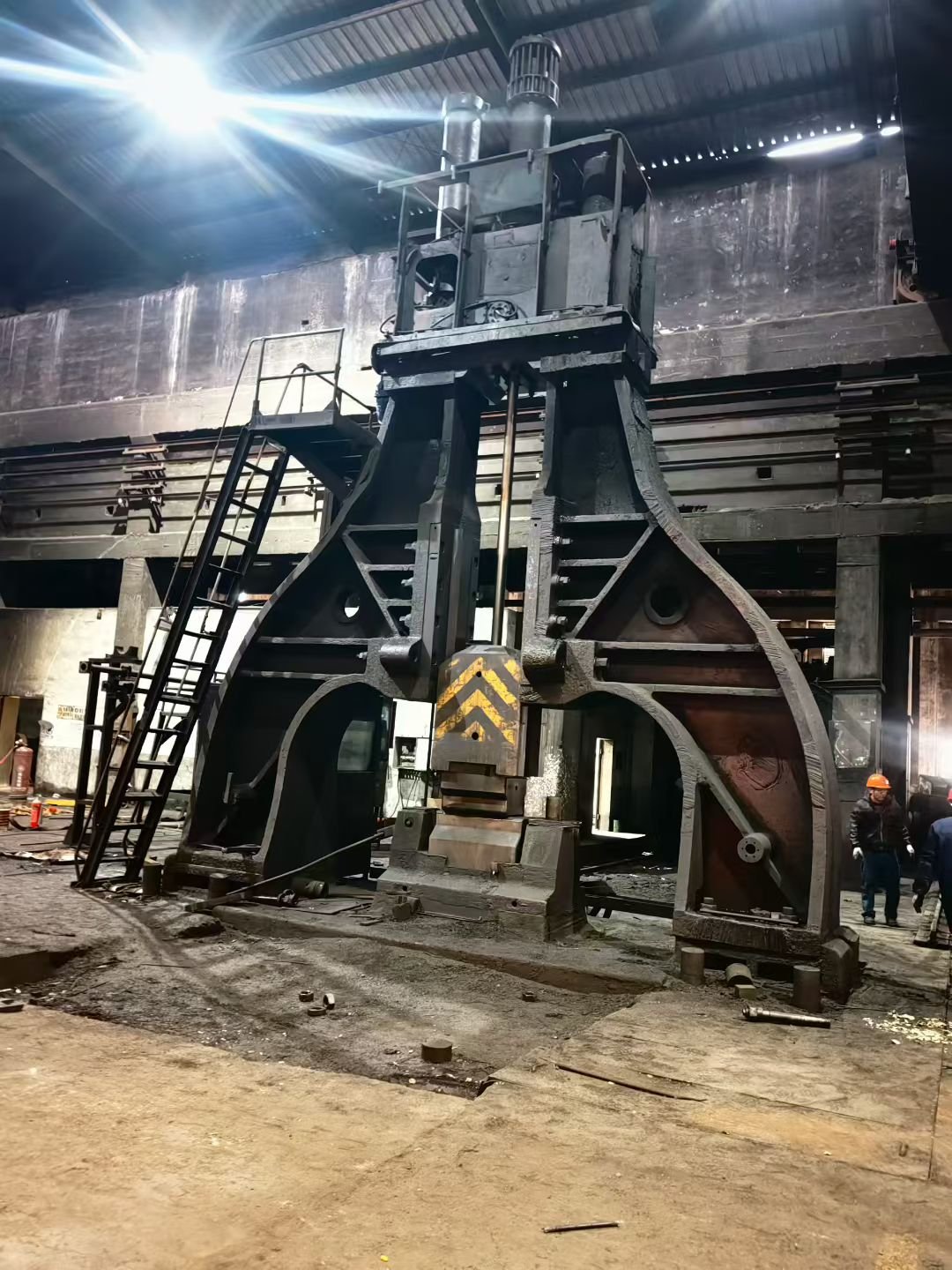
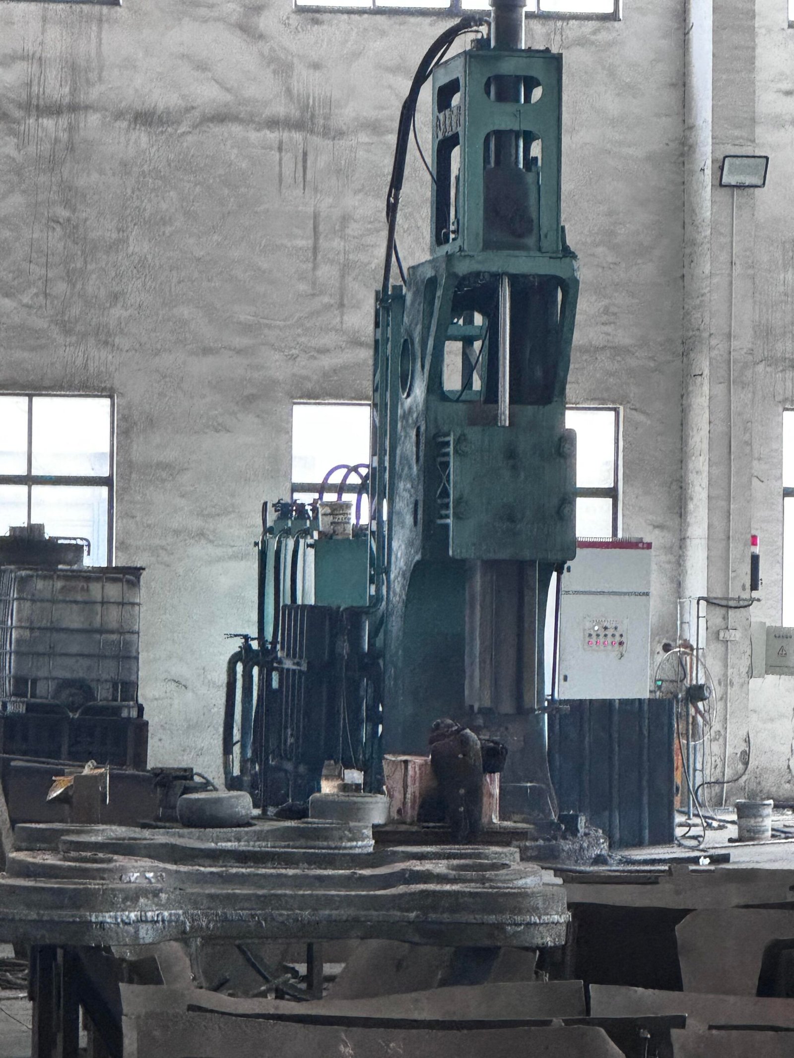
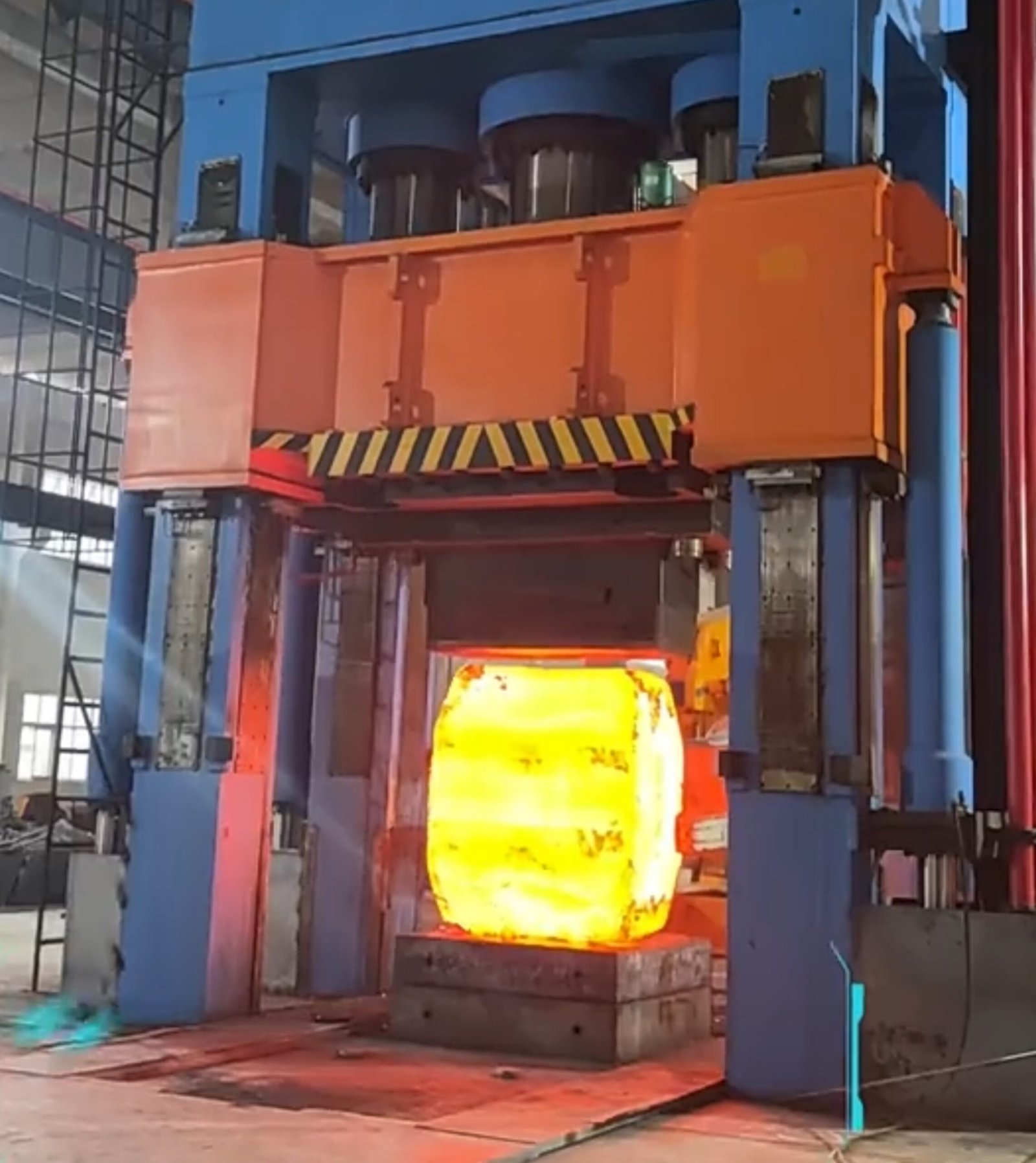
4,500-tonForging Press
Upsetting
Drawing-Out
Forging Manipulators
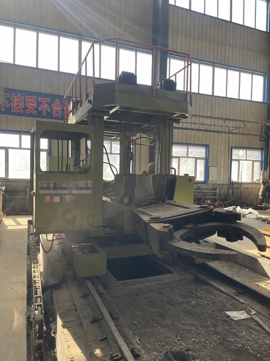
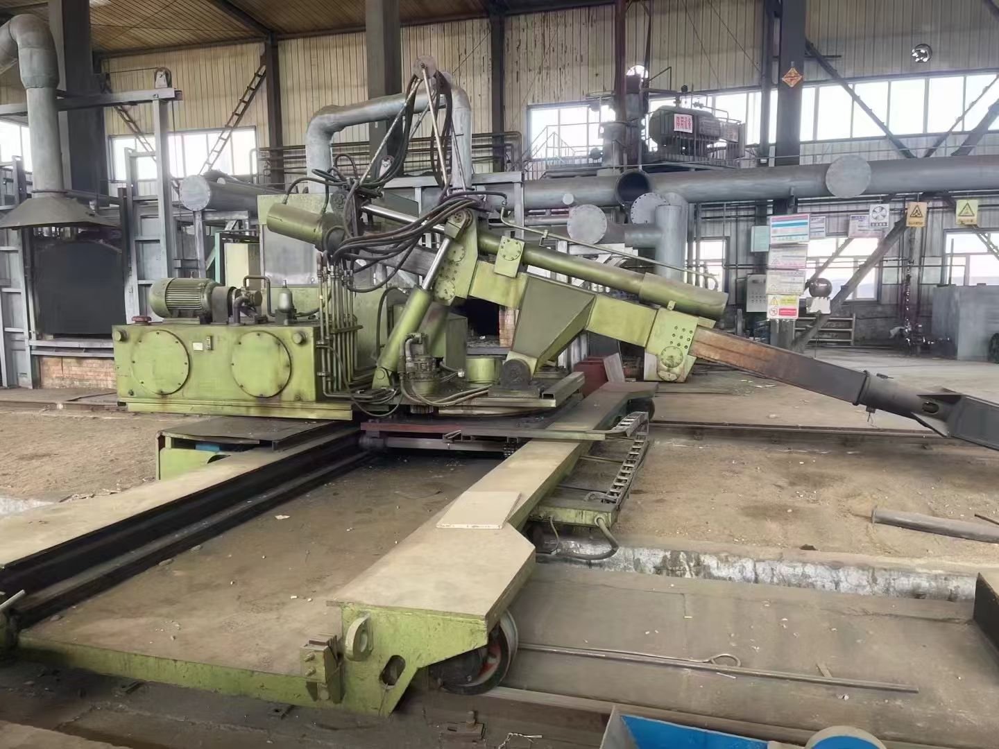
Blanks for Further Machining
Shafts & Stepped Shafts
Discs & Round Blanks
Blocks & Rectangular Blanks
Sleeves & Ring Blanks
Schematic forms. Final geometry and supply scope are reviewed to the drawing.
Typical Stepped-Shaft Forging
Billet Preparation & Heating
Prepare the stock and heat it for the selected forging route.
Upsetting
Where required, shorten the heated billet and increase its cross-section before drawing out.
Drawing-Out / Cogging
Apply overlapping press reductions along the billet, with axial feed and rotation between strokes.
Shoulder Forming
Locally reduce the section to establish the shaft shoulders and journals.
Stepped-Shaft Forging
Continue drawing individual sections to the required stepped blank, retaining machining stock.
Rounding & Straightening
Turn and work the blank to refine roundness, then correct straightness as required.
Cooling & Heat Treatment
Follow the material-specific cooling route and specified heat treatment.
Machining & Inspection
Machine to the agreed scope; check dimensions and specified material properties or soundness.
Forging Ratio for Shaft Sections
A0: reference starting area.
Af: forged section area, before machining.
For solid round sections:
R = (D0 / Df)2
(200 / 100)2 = 4:1
Cross-sectional area reduction = 75%.
Example for a drawing-out stage, not a claimed product size or a universal acceptance value.
Review Each Shaft Section
Upsetting reduces height and increases section. Record the height change separately.
Assess the relevant shaft sections and state the starting-stock basis. Required reduction and treatment of combined stages follow the agreed specification.
A forging ratio does not replace specified heat treatment, mechanical testing or internal-soundness inspection.
Send the Drawing.
Define the Forging Route.
- Drawing or 3D model
- Material grade & standard
- Order quantity
- Machining & inspection requirements