
DESIGN · TECHNICAL ARTICLE
Stainless Steel Elbow Design
How bend angle, centreline radius, wall behaviour, end preparation and inspection requirements are coordinated for standard and drawing-defined stainless steel elbows.
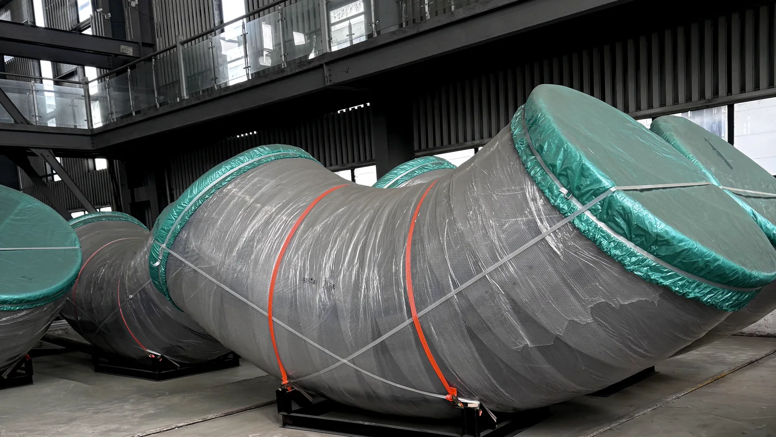
An elbow changes the direction of flow while preserving a controlled connection to the adjoining pipe. That simple description hides several linked design decisions: bend angle, centreline radius, tangent length, outside diameter, wall thickness, end preparation, material condition and the inspection method used to verify the formed geometry.
Standard 45-degree, 90-degree and 180-degree elbows can be defined efficiently when the order identifies the applicable standard and every required designation. Non-standard angles, extended tangents, heavy walls, special ends and welded constructions require a drawing-led review. In both cases, the design should show how the elbow connects to the piping system rather than treating it as an isolated curved object.
During forming, material on the outside radius is stretched while material on the inside radius is compressed. The resulting wall-thickness distribution, ovality and end geometry depend on the starting material, forming route and subsequent sizing. A design article therefore needs to connect geometric intent with a realistic manufacturing and inspection sequence.
Article Summary
- Define bend angle, centreline radius, tangent lengths and end-to-end dimensions from one consistent centreline model.
- Review outside-radius thinning, inside-radius compression and cross-section ovality as forming-related characteristics.
- Coordinate weld-end preparation and internal alignment with the adjoining pipe.
- Use the approved drawing and applicable fitting standard as complementary documents, particularly for non-standard geometry.
Elbow Geometry and Project Inputs
The design review starts with the piping route. The required change in direction, available installation envelope and locations of adjacent welds determine whether a standard elbow, a custom-angle elbow, an elbow with straight tangents or a fabricated segment is appropriate.
Dimensions should be provided in a way that can be reconstructed. A bend angle without a radius or centre-to-end dimension is incomplete. Likewise, an overall envelope without a defined centreline can be difficult to inspect because the dimensional origin is unclear.
- Nominal pipe size or drawing-defined outside diameter and ordered wall thickness.
- Bend angle, centreline radius, centre-to-end dimensions and any straight tangent length.
- Long-radius, short-radius or project-specific radius designation.
- Material grade, starting product form, heat-treatment condition and corrosion considerations.
- End preparation, bevel angle, root face, matching bore and any transition requirement.
- Dimensional tolerances for angle, centre-to-end, outside diameter, ovality and wall thickness.
- Applicable fitting, material, welding, examination and documentation requirements.
- Quantity, orientation marks, packing restrictions and any field-fit allowance.
Geometry and forming must be reviewed together: the centreline establishes the route, while wall and end controls establish manufacturability.
Design Review Workflow
A controlled workflow keeps piping-layout information, forming decisions and final inspection on the same dimensional basis.
- Confirm the piping route, required change in direction, connection points and available installation envelope.
- Define the centreline radius, bend angle, tangent lengths and overall dimensional references.
- Review starting material, wall thickness, forming route and the expected need for sizing or heat treatment.
- Coordinate weld ends, bore alignment and any transition to connected pipe or fittings.
- Agree dimensional, wall-thickness and examination requirements before the drawing is approved.
- Transfer the released drawing, datums, inspection points, marking and packing instructions to production.
Key Engineering Considerations
Centreline radius and envelope
The centreline radius is the fundamental geometric control for an elbow. A long-radius or short-radius designation may be sufficient when a recognized standard fully defines the item, but a custom elbow should show the numerical radius and the dimensional points used to establish it. Extended tangents should be dimensioned separately so they are not confused with the curved portion.
Installation space is checked against the complete outer envelope, including weld preparation and any straight ends. This prevents a design from fitting on the centreline drawing but interfering with equipment, steelwork or adjacent piping in the field.
Wall thickness, thinning and ovality
As the blank is bent or formed, the outer arc tends to thin and the inner arc tends to thicken. The neutral region between them does not necessarily remain centred. The design review should therefore identify the ordered wall thickness, any required minimum after forming and the inspection locations used to confirm the final condition.
Ovality is a change from the intended circular cross-section. Its importance depends on the connected pipe, service conditions, inspection basis and project standard. Measurement method matters: two diameters taken at right angles, a circumference measurement or a scanning method can produce different records unless the procedure is agreed.
End preparation and internal alignment
Weld-end details should match the adjoining pipe wall and the approved welding basis. Bevel angle, root face, bore and any counterbore or taper should be shown in section. For heavy-wall elbows, a controlled internal transition can be more important to fit-up than the outside appearance.
End squareness and angular orientation affect assembly. Where both ends contain non-symmetrical preparations or reference marks, the drawing should establish a common plane so production and site teams use the same orientation.
Standard and non-standard elbows
A standard elbow is reviewed against the stated standard, edition, size, schedule or wall and material specification. A non-standard elbow uses the approved drawing as the primary dimensional source. Standards may still define materials, tolerances, examinations and terminology, but they should not be used to hide a project-specific radius or angle.
Segmented, mitred or welded elbows should be identified explicitly because their weld layout, examination and flow geometry differ from a seamless or formed elbow. The manufacturing route is part of the technical definition, not an afterthought.
Numerical Design Example
90° elbow with a centreline radius of 1.5D
For an illustrative design diameter of D = 200 mm and a selected centreline relationship of R = 1.5D:
R = 1.5 × 200 = 300 mm
The centreline arc length for a 90° bend is:
L = πR ÷ 2 = π × 300 ÷ 2 ≈ 471 mm
The 471 mm result describes only the curved centreline. It does not include straight tangents, bevel extensions or forming allowances. It also does not define wall thickness, ovality or acceptance criteria; those remain project-specific.
Materials and Applicable Standards
Elbow requirements may draw on fitting dimensions, material specifications, welding rules and project piping standards. The exact combination is confirmed for each order.
| Review topic | Project design basis | Manufacturing handover |
|---|---|---|
| Geometry | Angle, radius, centre-to-end, outside diameter and tangent dimensions from the standard or approved drawing. | Forming tooling, cut length and sizing method are aligned with the same centreline model. |
| Material and wall | Grade, ordered wall, product form and heat-treatment condition. | Material identity and wall checks are maintained through forming and final inspection. |
| Ends | Bevel, root face, bore, transition and squareness. | End machining and fit-up gauges are planned before final inspection. |
| Dimensional acceptance | Angle, centre-to-end, ovality and diameter tolerances. | Inspection points, instruments and reporting format are identified. |
| Examination | Surface, volumetric or weld examination when applicable. | Hold points and documentation are included in the manufacturing route. |

Design Outputs and Manufacturing Handover
The released design package should define the elbow centreline, angle, radius, tangents, end preparations, material, wall basis, tolerances and required examination. A clear drawing avoids relying on a product name such as 90-degree elbow when the project actually requires extended ends, a special bore or a non-standard radius.
Production receives the approved revision together with the forming route, inspection characteristics and identification requirements. Inspection records should refer back to the same datums used by the drawing, particularly for angle and centre-to-end measurements.
When an elbow is part of a prefabricated assembly, its orientation should also be checked in the assembly coordinate system. This links the component design to the final spool or equipment interface rather than approving it only as a separate fitting.
Final dimensions, materials and manufacturing details are determined by approved drawings, applicable standards and project-specific requirements.
Frequently Asked Questions
Can NOKX review a non-standard elbow angle?
Yes. Provide the required angle, centreline radius, end coordinates or centre-to-end dimensions, material, wall thickness, ends and inspection requirements. The final geometry is released through an approved drawing.
What is the difference between centreline radius and outside radius?
Centreline radius follows the theoretical pipe centreline. Outside and inside radii depend on the pipe diameter and formed wall geometry. Drawings should state which reference is being dimensioned.
Does the arc-length example define the required blank length?
No. It describes the theoretical curved centreline only. Production length also depends on tangents, forming method, trim, end preparation and process allowance.
How should wall thinning be specified?
State the ordered wall basis, any required minimum after forming, the applicable acceptance document and the inspection method. Avoid an unsupported general note.
What should be sent with an elbow RFQ?
Send the piping or component drawing, outside diameter, wall, material, angle, radius, tangent lengths, end details, quantity, standard and required inspection documentation.
Related Products
Discuss Your Elbow Design Requirements
Send your drawing, material, quantity and applicable standard for a project-specific technical review.