
DESIGN · TECHNICAL ARTICLE
Reactor Vessel Design
A structure-focused guide to defining vessel geometry, nozzles, agitation interfaces, jackets, supports, drainage and manufacturing information for project review.
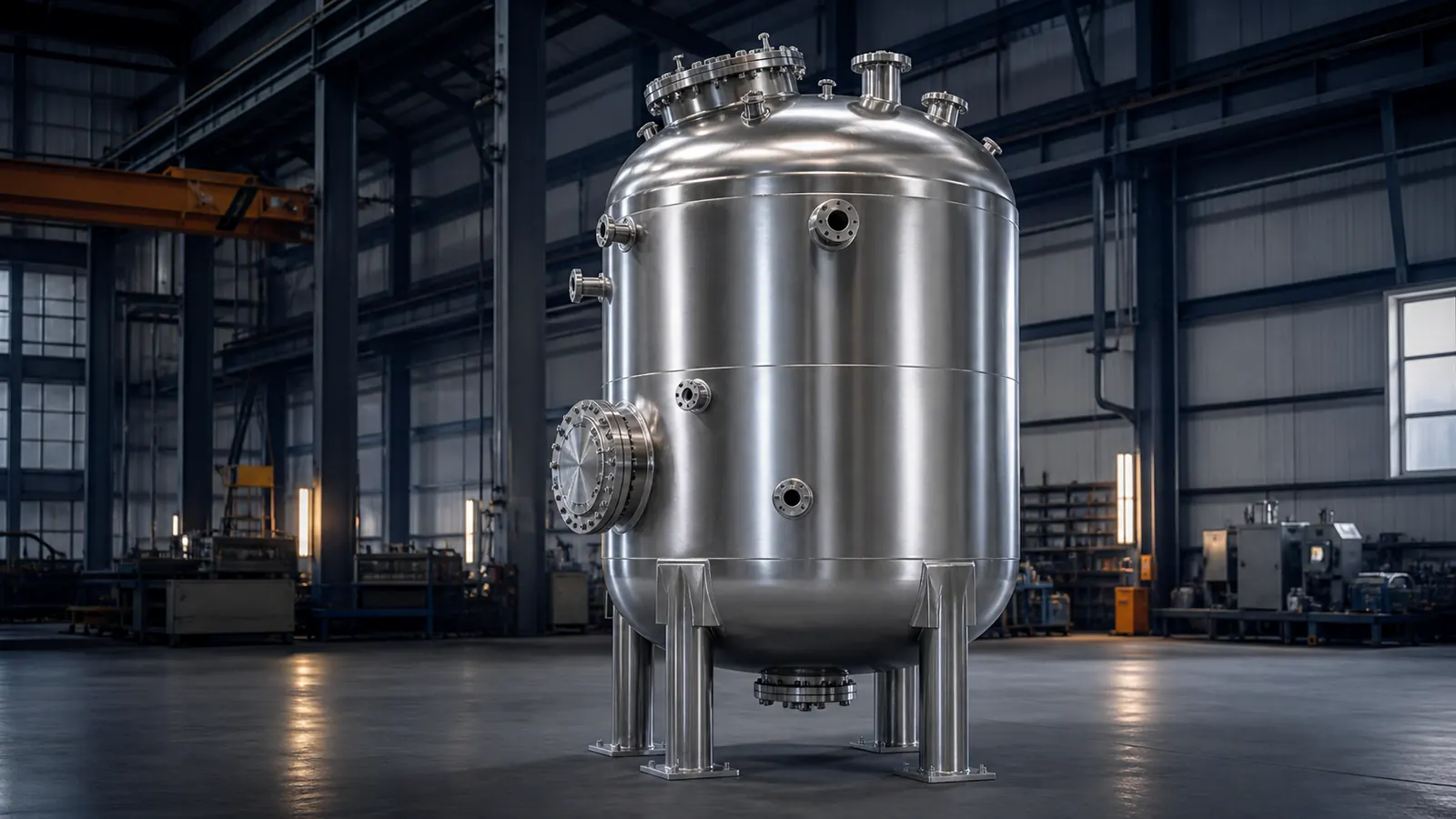
A reactor vessel brings process, mechanical and manufacturing requirements into one piece of equipment. The shell and heads establish the main envelope, but performance and maintainability also depend on nozzles, agitation, heat-transfer surfaces, supports, access openings, drainability and the arrangement of internal components.
This article focuses on product structure and the information needed for a responsible project review. It does not replace code calculations, process design or the work of an authorized pressure-equipment designer where those obligations apply. Design pressure, temperature, allowable stress, corrosion allowance, fatigue, external loads and regulatory certification must be established under the governing project rules.
For manufacturing coordination, a clear general arrangement is essential. It should show the vessel orientation, principal dimensions, connection schedule, support arrangement and the location of every interface that affects fabrication, inspection, transport or installation.
Article Summary
- Define process duty, vessel orientation, working volume and operating conditions before selecting the structural arrangement.
- Coordinate shell, heads, nozzles, manways, agitation support, jacket or coil, supports and lifting features as one system.
- Use nozzle schedules and orientation drawings to prevent interface conflicts.
- Separate structural explanation from code calculations and certification responsibilities.
Reactor Vessel Structure and Design Inputs
The first review identifies what the equipment must contain, mix, heat, cool, drain and clean. The medium, phase, viscosity, solids content, corrosiveness and cleaning method can influence vessel shape and internal access even before detailed mechanical calculations begin.
The second review identifies external interfaces. These include piping loads, agitator and gearbox loads, platforms, insulation, supports, lifting, transport restraints and site clearances.
- Process description, medium, phase, viscosity, solids content and cleaning or sterilization method.
- Required working volume, total geometric volume, liquid levels and vessel orientation.
- Design and operating pressure and temperature supplied under the approved project basis.
- Material grade, corrosion allowance, surface-finish and contamination-control requirements.
- Agitator type, speed, power, shaft arrangement and loads supplied by the equipment designer.
- Nozzle list, sizes, ratings, facing, projection, elevation and angular orientation.
- Jacket, half-pipe coil, internal coil or other heat-transfer arrangement.
- Manway, sight glass, instrument, sampling, vent, drain and relief-system interfaces.
- Support type, external loads, lifting, transport, insulation and installation constraints.
- Applicable pressure-equipment rules, inspection plan, documentation and certification responsibility.
Structure map: vessel body, process connections, agitation, heat transfer and supports must be coordinated before fabrication drawings are released.
Design Review Workflow
The review progresses from process duty to arrangement, interfaces and manufacturing information. Formal code design and certification remain subject to the governing project rules.
- Confirm the process description, vessel function, orientation, working volume and cleaning concept.
- Establish the governing pressure-equipment basis and identify the responsible design and certification parties.
- Develop the shell, head, access, agitation, heat-transfer and support arrangement.
- Create a nozzle schedule and orientation drawing with elevations, projections and angular positions.
- Review manufacturing access, weld layout, examination access, drainability, transport and installation.
- Release approved arrangement and fabrication information with the required inspection and documentation plan.
Key Engineering Considerations
Shell, heads and usable volume
The vessel outline depends on the relationship between total geometric volume and intended working volume. Freeboard may be needed for agitation, foaming, gas space or process transitions. Head geometry contributes volume and affects drainage, support arrangement and manufacturing sequence.
Vertical vessels often support gravity drainage and a compact floor footprint, while horizontal arrangements may suit other process or installation constraints. The selection should follow process and site requirements rather than appearance alone.
Nozzles, manways and orientation
A nozzle schedule should identify each connection by tag, service, size, rating or connection basis, projection, elevation and angular orientation. Orientation is best shown on a dedicated plan view with a zero-degree reference.
Manways and inspection openings require clearance for covers, tools and personnel access. Nearby nozzles, agitator supports, jackets and platforms should be reviewed for interference before shell openings are finalized.
Agitation and internal components
An agitator affects the top-head opening, support stiffness, shaft alignment and internal clearances. Baffles, dip pipes, coils and spargers must be coordinated with the rotating envelope and with one another. The equipment supplier should provide the relevant loads and interface details.
Internal components should also be reviewed for assembly sequence and inspectability. A design that is geometrically possible may still be impractical if an internal part cannot pass through the opening or cannot be welded and examined after the shell is closed.
Jackets, coils, supports and drainage
Heat-transfer arrangements introduce additional connections, welds and pressure boundaries. A conventional jacket, half-pipe coil or internal coil should be selected against process duty, cleaning, access and the governing design basis. The webpage does not assign a universal pressure or temperature limit.
Supports and lifting features must account for approved load cases, including empty, operating, test, transport and installation conditions as applicable. Drain connections and internal slopes should allow the agreed level of drainability.
Regulatory and project responsibility
Pressure-vessel rules can govern materials, design, fabrication, examination, testing, inspection, certification and marking. The applicable code edition and legal obligations depend on destination and intended service.
NOKX project communication distinguishes structural and manufacturing coordination from formal code calculations or certification. No website example should be used as a substitute for an approved pressure-equipment design package.
Numerical Design Example
Four equally spaced nozzles
If four nozzles are required at one elevation and are equally spaced around the shell, the angular interval is:
360° ÷ 4 = 90°
With nozzle N1 defined at 0°, the nominal centreline positions are 0°, 90°, 180° and 270°. A project drawing must still define the zero-degree reference, viewing direction, nozzle projection, elevation and whether any connection is offset for access or process reasons.
The calculation describes orientation only. It does not establish opening reinforcement, allowable loads, pressure design or nozzle-neck thickness.
Materials and Applicable Standards
Reactor-vessel projects may involve pressure-equipment, material, welding, examination and customer specifications. The approved project documentation determines which rules apply.
| Review topic | Project design basis | Manufacturing handover |
|---|---|---|
| General arrangement | Orientation, volume basis, shell, heads, supports and access from the approved arrangement. | Fabrication drawings and sequence are developed from the released configuration. |
| Pressure-equipment basis | Applicable jurisdiction, code edition and responsible design or certification parties. | Manufacturing and inspection activities follow the approved code package where applicable. |
| Materials and surfaces | Material grade, corrosion allowance, finish and contamination controls. | Material traceability, weld preparation and surface treatment are planned. |
| Connections and internals | Nozzle schedule, agitation interfaces, internals and heat-transfer arrangement. | Openings, fit-up, access and inspection sequence are coordinated. |
| Testing and documentation | Approved examination, testing, inspection and document requirements. | Hold points and records are linked to vessel and component identification. |
Design Outputs and Manufacturing Handover
Typical outputs include a general arrangement, nozzle orientation drawing, nozzle schedule, interface details, support and lifting information, internal-component arrangement and a list of governing documents. Detailed calculations and code forms are included only when they are part of the agreed responsibility and are prepared by qualified parties.
Manufacturing handover should identify the approved revision, material requirements, weld layout, sequence-sensitive operations, inspection access and test configuration. Interfaces supplied by agitator, instrument or piping vendors should be frozen or formally controlled before fabrication reaches an irreversible stage.
The final document package is project-specific. Material records, dimensional reports, welding and examination records, test documents and marking information are provided when applicable to the order and agreed inspection requirements.
Final dimensions, materials and manufacturing details are determined by approved drawings, applicable standards and project-specific requirements.
Frequently Asked Questions
Is this page a pressure-vessel design calculation?
No. It explains product structure and the inputs needed for project review. Formal pressure design, code calculations and certification must follow the applicable jurisdiction and approved engineering responsibility.
What information is needed for a reactor-vessel enquiry?
Provide process duty, medium, working volume, pressure and temperature basis, material, agitation information, connections, heat-transfer arrangement, support concept, applicable rules, quantity and documentation requirements.
Can nozzle positions be customized?
Yes, subject to arrangement, process, structural, fabrication and inspection review. Positions should be defined by elevation, projection and angular orientation from a stated datum.
Can a jacket and internal coil be shown on the same concept?
They can be evaluated as project features, but the final arrangement depends on process duty, cleaning, access, pressure boundaries and the approved design basis.
How are unpublished related products handled?
The article does not show inactive buttons. Relevant vessel, tube, flange or fitting products will appear only after product pages are published.
Related Products
Discuss Your Reactor Vessel Design Requirements
Send your drawing, material, quantity and applicable standard for a project-specific technical review.