
DESIGN · TECHNICAL ARTICLE
Hot-Die Forging Design
How billet size, preform geometry, die fill, parting line, flash, radii, machining allowance and process sequence are coordinated for drawing-defined hot forgings.
Hot-die forging design converts a finished-part requirement into a sequence of material shapes that can be formed repeatedly. The finished component may look compact, but the process has to account for billet volume, heating, scale, preform distribution, die fill, flash, trimming, heat treatment and machining stock.
A strong design begins with the final functional geometry and works backwards. Machined surfaces, holes, thin sections, bosses, ribs and transitions are reviewed to decide which features should be forged near-net, which should remain solid for later machining and which radii or draft features are needed for removal from the dies.
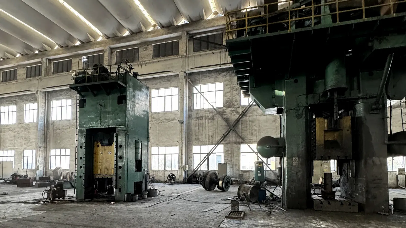
NOKX manufacturing information includes a 6,000-ton hot-die forging press with a 1.8 × 1.8 m working table. These equipment facts support process planning, but they are not presented as a universal component-size limit. Every forging is reviewed against material, geometry, projected area, stroke, tooling and the approved manufacturing route.
Article Summary
- Start from the approved finished geometry and create a forging model with realistic machining stock, draft and radii.
- Distribute billet material through preform and blocker stages before final die fill.
- Review parting line, flash land, trimming, grain-flow intent and defect-sensitive transitions.
- Connect design decisions to heating, press operation, heat treatment, machining and inspection.
Forging Geometry and Project Inputs
The input package should include the final machined drawing or a sufficiently detailed functional model. Critical load paths, machined surfaces and areas that must remain continuous should be identified so the forging outline is not developed only from external appearance.
Material information is essential because flow stress, forgeability, heating window, scale behaviour and heat-treatment route vary between alloys. Annual quantity and repeatability expectations influence whether dedicated tooling and multi-stage preforms are appropriate.
- Finished drawing or 3D model, revision, units, datums and functional surfaces.
- Material grade, product specification, heat-treatment condition and traceability requirements.
- Required mechanical properties, test location and grain-flow or fibre-flow expectations where applicable.
- Machining allowance, dimensional tolerance and surfaces that must remain as-forged.
- Quantity, batch size, repeat-order expectation and tooling-life considerations.
- Parting-line restrictions, flash limitations, cosmetic surfaces and identification areas.
- Inspection, NDT, mechanical testing, documentation and third-party requirements.
- Packing, preservation and protection of machined reference surfaces.
Hot-Die Forged Lifting Hook
Rotate a new representative hook model to examine section changes, the eye, load path and the tapered working end.
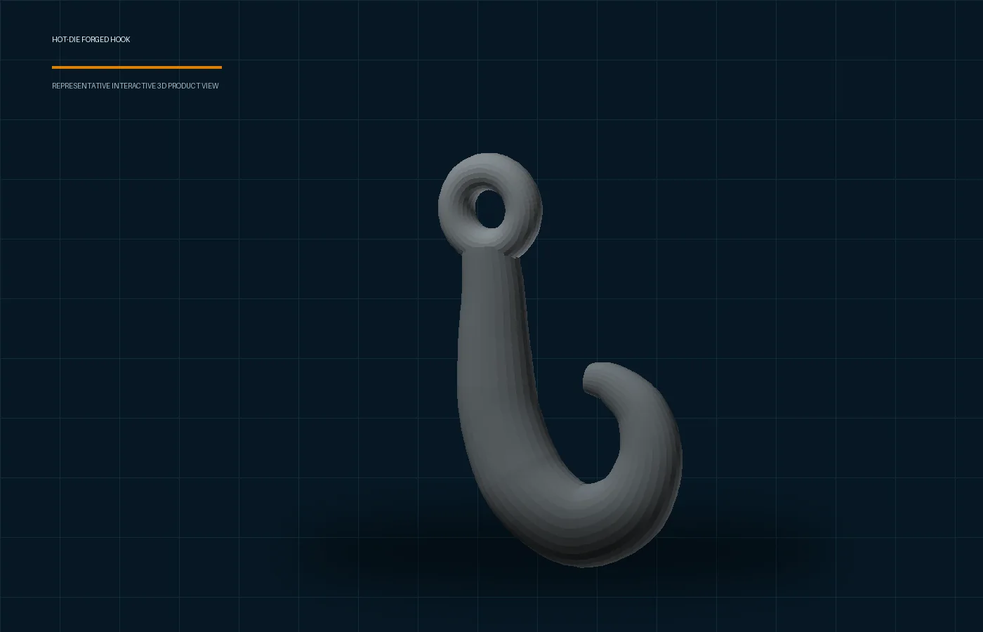
Representative product geometry for design discussion; it is not a finite-element result or a rated lifting component.Drag to rotate · Scroll page normally on touch devices
Design Review Workflow
The design workflow uses volume control and progressive material distribution to reduce late tooling changes and avoid relying on the finishing impression to correct every shape.
- Review the finished component, load-sensitive features, datums, machined surfaces and required properties.
- Develop the forging outline with machining stock, draft, radii, fillets and a practical parting line.
- Estimate billet volume and mass, including process allowances appropriate to the selected route.
- Design billet, preform and blocker shapes to distribute material before the finishing impression.
- Review die fill, flash, trimming, heating, press sequence, handling and heat-treatment requirements.
- Release forging, tooling and inspection information under controlled revision for production trials and approval.
Key Engineering Considerations
Parting line, draft and die release
The parting line affects die construction, material flow, flash location and trimming. A simple flat parting line can improve tooling and inspection, but the component geometry may require a stepped or shaped line. The selected line should avoid placing flash on critical machined or highly loaded surfaces where practical.
Draft permits the forged part to leave the die. Draft requirements depend on geometry, die depth, material, surface and process. Internal pockets generally require particular attention because they can lock the forging or create severe die wear.
Radii, fillets and material flow
Sharp internal corners restrict material flow and increase local tooling stress. External corners can cool quickly and may not fill as intended. Forging radii and fillets should therefore be reviewed as process features before machining stock is applied.
Material should be directed into bosses, hooks, ribs and thick sections progressively. A preform that resembles the final part but contains material in the wrong location can still create laps, underfill or excessive flash during finishing.
Machining allowance and datum strategy
Machining stock should cover forging variation, scale and heat-treatment movement without adding unnecessary material. Different surfaces may require different stock because their forging accessibility, final tolerance and relationship to datums are not the same.
Reference pads or stable as-forged surfaces can help establish machining. The forging drawing should identify which datums belong to the final part and which temporary references are used only during manufacturing.
Tooling, press and process sequence
Projected area, material flow stress, impression depth and flash influence required forming load. The 6,000-ton press and 1.8 × 1.8 m table are reviewed together with tooling footprint, handling space and the planned sequence; a single equipment number does not approve a part automatically.
The route may include billet preparation, heating, descaling, preforming, blocking, finishing, trimming, heat treatment, cleaning, inspection and machining. Sequence planning should identify where dimensions or defects become inaccessible later.
Simulation-style communication
Process visualizations can show intended progression from billet to finished forging. The original 3D hook graphic on this page is labelled conceptual because it does not contain a validated material model, boundary conditions, mesh or measured process data.
If actual finite-element results are later supplied and approved, they should state the software, material model, assumptions and result type. Concept art must never be presented as a calculated strain, temperature or die-stress result.
Numerical Design Example
Illustrative cylindrical billet volume and mass
For a cylindrical billet with diameter 150 mm and length 120 mm:
V = π × (75 mm)² × 120 mm ≈ 2,120,600 mm³
V ≈ 2,121 cm³
Using an illustrative density of 7.9 g/cm³, the theoretical mass is approximately:
2,121 × 7.9 ÷ 1,000 ≈ 16.8 kg
This is a geometry example, not a released billet size. Production mass also considers material grade, scale, flash, trimming, testing allowance and the approved forging route.
Materials and Applicable Standards
Forging projects combine customer drawings, material specifications, heat-treatment requirements, testing and dimensional acceptance. The approved order documents define the controlling basis.
| Review topic | Project design basis | Manufacturing handover |
|---|---|---|
| Finished geometry | Functional surfaces, datums, tolerances and required properties from the approved part drawing. | The forging model allocates machining stock and process features without changing function. |
| Material | Grade, starting stock, heat treatment and test requirements. | Material identity and heat or batch traceability are maintained through the route. |
| Forging design | Parting line, draft, fillets, preforms, blocker, finisher and trimming basis. | Tooling and press operations follow controlled drawings and trial records. |
| Machining handover | Machining allowance, references and surfaces requiring protection. | Machining setup and dimensional inspection use agreed datums. |
| Inspection | Surface, volumetric, mechanical and dimensional requirements where applicable. | Hold points and records are included in the project-specific route. |
Design Outputs and Manufacturing Handover
Design outputs may include a finished-part review, forging drawing, 3D forging model, billet calculation, tooling concept, process sequence, heat-treatment basis and inspection characteristics. Tooling drawings and process parameters remain controlled manufacturing documents.
Production handover identifies the approved material, billet, heating and operation sequence, lubrication or descaling requirements, trimming, heat treatment, cleaning and inspection stages. Trial results are reviewed before repeat production where the project route requires approval.
The final forging is evaluated against the agreed as-forged and machined requirements. Documentation is supplied according to the order and may include material traceability, heat-treatment records, inspection results and mechanical-test records when applicable.
Final dimensions, materials and manufacturing details are determined by approved drawings, applicable standards and project-specific requirements.
Frequently Asked Questions
Does the hook visual show actual DEFORM results?
No. It is an original conceptual 3D process visualization. It shows relative stages only and does not claim calculated strain, temperature, load or defect prediction.
Can NOKX review a drawing-defined non-standard forging?
Yes. Provide the finished drawing or model, material, quantity, heat treatment, properties, machining allowance, testing and inspection requirements for project review.
Does a 6,000-ton press define the maximum part size?
No. Equipment force is one input. Geometry, projected area, material, tooling, stroke, table space, handling and the complete process route must also be reviewed.
Why are preform and blocker stages used?
They distribute material before the finishing impression, helping fill thick or offset features and reducing reliance on excessive flash or a single severe forming step.
What should be included in an RFQ?
Send the finished drawing or model, material, quantity, annual demand if known, heat treatment, mechanical properties, machining and inspection requirements.
Related Products
Discuss Your Hot-Die Forging Design Requirements
Send your drawing, material, quantity and applicable standard for a project-specific technical review.