
DESIGN · TECHNICAL ARTICLE
Stainless Steel Flange Design
A practical engineering guide to reviewing flange geometry, sealing interfaces, bolt patterns, materials and manufacturing details for standard and non-standard projects.
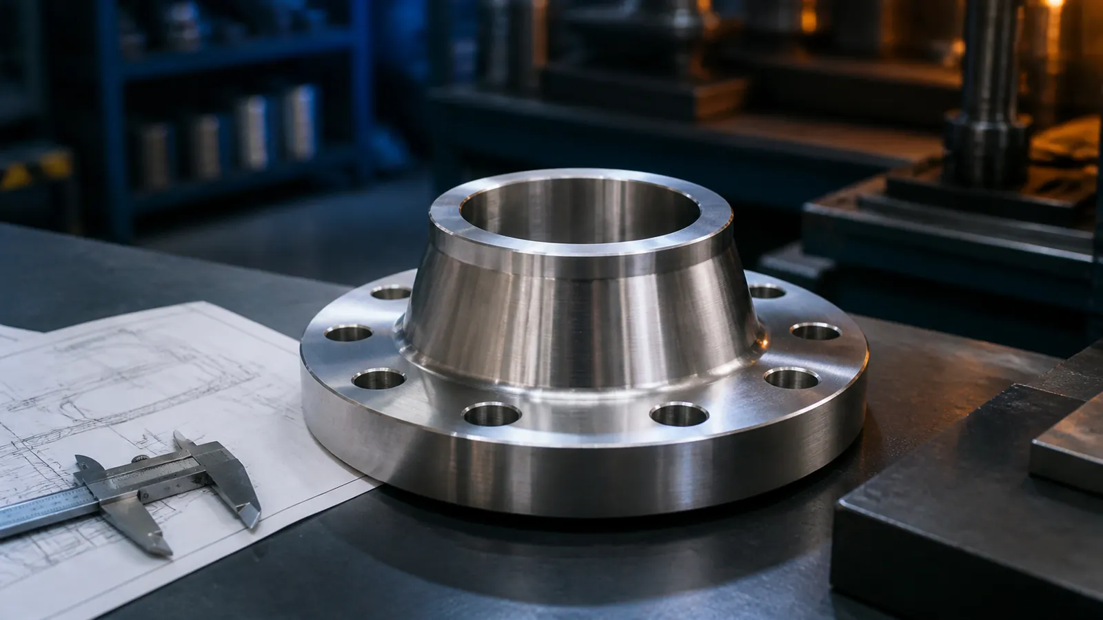
Flange design is the point where piping geometry, sealing performance, bolting and manufacturing accuracy meet. A flange can match a familiar standard designation and still require careful project review because the connected pipe, equipment nozzle, gasket, fasteners, service medium or inspection plan may introduce requirements that are not visible in a short purchase description.
For a standard flange, the review begins by confirming the governing dimensional standard, nominal size, pressure designation, material grade, facing and bore. For a non-standard flange, the same review becomes drawing-led: every functional surface, transition radius, bolt-hole location and machining allowance must be coordinated with the mating component and the intended production route.
NOKX uses the approved drawing as the controlling design document. The purpose of the review is not to force a custom component into a standard catalogue shape, but to identify which dimensions control fit, sealing and load transfer, and then hand those requirements to forging, heat treatment, machining and inspection in a form that can be checked.
Article Summary
- Define the mating pipe, equipment connection, gasket and bolting before finalizing the flange outline.
- Control the relationship between outside diameter, bore, thickness, hub transition, bolt circle and sealing face.
- Separate standard-derived dimensions from project-specific dimensions so that non-standard details remain visible.
- Plan forging stock, heat treatment, machining datums and inspection points before production starts.
Flange Structure and Project Inputs
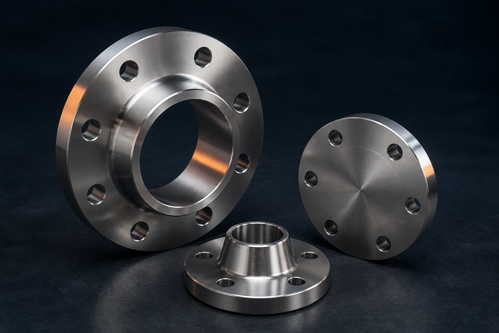
The first design task is to identify the flange family. Weld-neck flanges transfer the pipe wall into a tapered hub and require a bore and weld-end transition coordinated with the pipe. Slip-on flanges use a different fit-up and weld arrangement. Blind flanges close an opening and therefore have no through bore. Threaded, socket-weld, loose and custom equipment flanges introduce their own interface and manufacturing questions.
A complete project input package should show both the flange itself and the component it connects to. A single isolated flange drawing may not reveal whether a bore step, gasket recess, hub taper or bolt-hole orientation is functionally important.
- Flange type, nominal size or drawing-defined outside diameter and overall thickness.
- Pipe outside diameter, wall thickness, bore transition and weld-end preparation where applicable.
- Bolt-circle diameter, number of holes, hole diameter, orientation and any tapped-hole requirement.
- Facing type, gasket geometry, surface-finish requirement and the sealing-face protection method.
- Material grade, product form, heat-treatment condition and corrosion or temperature considerations.
- Applicable dimensional, material, welding, examination and acceptance standards.
- Quantity, marking, documentation, packing and any third-party inspection requirement.
Design relationship: functional dimensions are reviewed together rather than as isolated numbers.
Design Review Workflow
The review workflow converts customer requirements into a controlled manufacturing basis. Clarifications should be resolved before forging stock or machining datums are fixed.
- Confirm the mating components, flange family, design standard and project-specific deviations.
- Build a dimension map covering OD, bore, thickness, hub, facing, bolt circle and hole orientation.
- Review material form, heat treatment, corrosion considerations and traceability requirements.
- Establish forging or plate route, machining stock, datums, tool access and surface protection.
- Issue the drawing for customer review and record every approved revision.
- Transfer the approved drawing, inspection characteristics and marking requirements to production.
Key Engineering Considerations
Geometry, bore and hub transition
The bore is not merely a central opening. On a weld-neck flange it should be reviewed against the pipe inside diameter, wall thickness and weld preparation so that the transition does not create an unintended internal step. The hub length, taper and blend radius also influence how material flows during forging and how the part can be supported during machining.
For a custom flange, datums should be explicit. A practical drawing normally identifies the sealing face, bore axis and a reference bolt hole or clocking line. These references allow machining and inspection teams to reproduce the same orientation without interpreting the drawing differently.
Bolt pattern and assembly orientation
Bolt-circle diameter, hole count and hole diameter must be treated as one pattern. A correct circle with an incorrect angular starting position can prevent assembly where a flange is clocked to an equipment nozzle. Slotted holes, tapped holes and mixed hole sizes require direct callouts rather than general notes.
The design review also checks edge distance, tool clearance and access for nuts or tensioning equipment. These details become especially important on compact equipment flanges or where nearby nozzles and supports restrict assembly space.
Facing, gasket and surface control
The facing should be coordinated with the gasket type and mating face. Raised faces, flat faces, ring-joint grooves and custom recesses require different machining and inspection methods. A surface-finish symbol should identify the controlled area and the specified measurement basis instead of relying on a general statement such as good finish.
Protection after final machining is part of the design handover. Sealing faces may require covers, separators or non-abrasive wrapping so that machining quality is maintained through inspection, marking and export packing.
Standard flange versus drawing-led flange
A standard designation can efficiently define many dimensions, but any modified bore, unusual material, special facing, non-standard thickness or custom drilling pattern should be shown explicitly. The drawing should make clear which standard remains applicable and which dimensions are replaced by project requirements.
For non-standard work, the drawing itself becomes the primary dimensional source. Relevant standards still guide material, welding, testing and terminology, but they should not be cited in a way that implies that an unlisted custom geometry is a standard catalogue item.
Numerical Design Example
Eight-hole bolt pattern
For eight equally spaced holes, the angular pitch is:
360° ÷ 8 = 45°
If the first hole centre is defined at 0°, the remaining centres occur at 45°, 90°, 135°, 180°, 225°, 270° and 315°. This simple calculation does not define the bolt-circle diameter or hole size; those values still come from the applicable standard or approved drawing.
On an equipment connection, the drawing should also state whether a hole or a gap between holes is aligned with the vertical or horizontal reference axis. Without that clocking instruction, two geometrically identical eight-hole patterns may be assembled in different orientations.
Materials and Applicable Standards
Applicable documents depend on the flange type, project location and purchasing specification. The following table shows how standards are used during review without replacing the approved drawing.
| Review topic | Project design basis | Manufacturing handover |
|---|---|---|
| Dimensional standard | Confirm the edition, size range, pressure designation and flange family referenced by the order. | Record all dimensions that remain standard and identify every project-specific override. |
| Material specification | Confirm grade, product form, heat treatment and supplementary requirements. | Maintain material identification from incoming stock through machining and final marking. |
| Facing and gasket | Confirm facing geometry, finish and the compatible gasket or sealing element. | Define machining, inspection and protection of the sealing surface. |
| Bolting interface | Confirm bolt diameter, hole pattern, thread requirement and assembly clearance. | Inspect BCD, angular spacing, hole diameter and clocking from the agreed datum. |
| Welding and examination | Confirm weld-end geometry and any applicable welding or NDT requirements. | Transfer prepared-end dimensions and examination hold points to the routing. |
Design Outputs and Manufacturing Handover
A useful flange design output is more than a finished outline. It should identify the revision, drawing units, material basis, applicable standards, critical datums, machined surfaces, tolerances, facing requirements and inspection characteristics. Notes should distinguish mandatory requirements from reference information.
The production handover links each design feature to a process. Forging staff need the stock and shape basis; heat-treatment staff need the material and condition; machining staff need datums, stock and surface requirements; inspection staff need measurable characteristics and acceptance criteria. This sequence reduces the risk that a critical sealing or assembly dimension is discovered only at final inspection.
For repeat orders, the approved drawing and revision history provide continuity. If the customer changes the mating pipe, gasket, bolt pattern or equipment interface, the change should trigger a fresh review rather than being treated as a purchasing note.
Final dimensions, materials and manufacturing details are determined by approved drawings, applicable standards and project-specific requirements.
Frequently Asked Questions
Can NOKX review a flange that does not match a catalogue size?
Yes. A non-standard flange can be reviewed from the customer drawing, mating-component information, material specification and inspection requirements. The final geometry remains subject to technical confirmation and an approved drawing.
Which information is most important for a weld-neck flange?
Provide the pipe outside diameter and wall thickness, flange bore, weld-end preparation, hub geometry, facing, bolt pattern, material and applicable standard. A section view is strongly recommended.
Can a standard flange include a custom bore or drilling pattern?
It can be manufactured as a drawing-defined component, but the modification should be identified clearly. The finished item should not be described only by the unchanged standard designation.
How is bolt-hole orientation controlled?
The drawing should define a reference axis and state whether a hole centre or the space between holes aligns with that axis. Inspection then uses the same datum.
What should be included in an RFQ?
Send the drawing or dimensional sketch, flange type, material, quantity, mating connection, standard, service conditions, inspection scope and required documentation.
Related Products
Discuss Your Flange Design Requirements
Send your drawing, material, quantity and applicable standard for a project-specific technical review.