
DESIGN · TECHNICAL ARTICLE
Open-Die Forging Design
A practical guide to planning upsetting, drawing, fullering, punching, mandrel work, forging ratio, machining stock and inspection for large drawing-defined blanks.
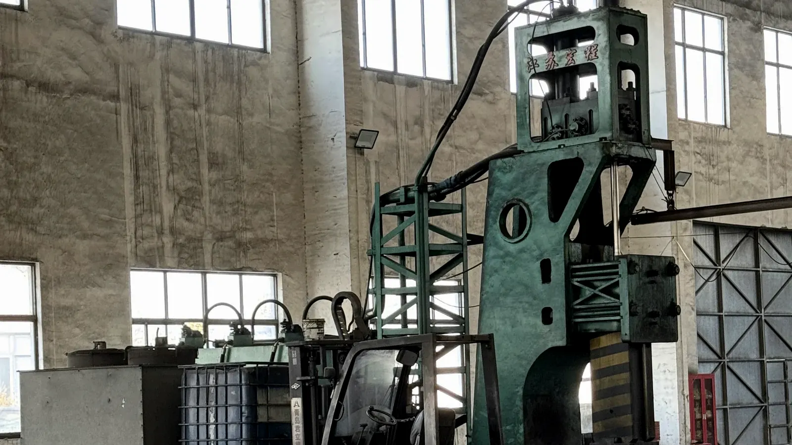
Open-die forging shapes heated stock between relatively simple tools rather than enclosing the material in a fully shaped impression. The process can produce shafts, rings, discs, blocks, hubs, hollow components and pre-machining blanks in a wide range of drawing-defined forms.
Design is centred on the sequence of deformation. Upsetting increases cross-section and reduces height; drawing reduces cross-section and increases length; fullering and edging move material locally; punching and mandrel operations create or enlarge holes. Each operation changes geometry, temperature and material flow, so the route should be planned as a connected sequence.
NOKX manufacturing information includes a 1,000-ton open-die forging hammer. The equipment supports process planning but does not establish a universal maximum component size. Stock dimensions, material, forging ratio, tool access, handling, heating, required properties and inspection all influence feasibility.
Article Summary
- Develop the forging route around required final dimensions, machining stock, properties and test locations.
- Use upsetting, drawing and local material-distribution operations in a controlled sequence.
- Track cross-sectional reduction and forging ratio from an explicitly defined starting condition.
- Plan reheating, handling, heat treatment, machining references and inspection before production.
Open-Die Forging Structure and Project Inputs
The enquiry should identify whether the required delivery is an as-forged blank, rough-machined component or finished-machined part. This affects stock allowance, datums, inspection and the dimensional information shown on the forging drawing.
Required mechanical properties and test locations can influence the route as much as external geometry. A test coupon taken from an extension, a prolongation or a separate sample should be agreed before stock size and cut length are fixed.
- Finished or rough-machined drawing, delivery condition, revision, datums and units.
- Material grade, starting-stock form, heat-treatment condition and traceability requirements.
- Required forging ratio or reduction basis where specified by the project documents.
- Mechanical properties, test direction, test location and sampling method.
- As-forged dimensions, machining allowance, tolerances and surfaces requiring cleanup.
- Required operations such as upsetting, drawing, fullering, punching, mandrel expansion or ring work.
- Surface, ultrasonic, dimensional and other inspection requirements where applicable.
- Quantity, identification, preservation, packing and third-party inspection requirements.
Open-Die Forged Stepped Shaft
Rotate a new shaft model to review its journals, stepped transitions, central body and machining-stock distribution.
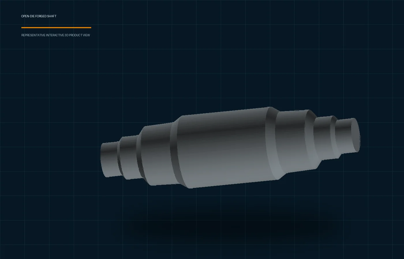
Representative open-die forging geometry; final stock, transitions and test locations follow the approved drawing and process route.Drag to rotate · Scroll page normally on touch devices
Design Review Workflow
The route is developed from the required delivery shape and properties, then checked against stock, tools, handling, heating and inspection.
- Review final geometry, delivery condition, machining allowance, properties and inspection requirements.
- Select starting stock and define the initial heat or batch traceability basis.
- Plan upsetting, drawing, fullering, punching, mandrel or local operations in a controlled sequence.
- Calculate required cross-sectional changes and the project-defined forging-ratio basis.
- Coordinate reheating, intermediate dimensions, handling, heat treatment and sampling.
- Release forging and inspection information, then record actual dimensions and heat treatment through production.
Key Engineering Considerations
Starting stock and deformation route
Starting-stock shape influences the first operations. Billet, ingot, bar or preformed stock can require different conditioning and reduction. The route should avoid creating a geometry that later tools cannot grip, support or reheat uniformly.
Intermediate dimensions are useful process controls. They allow the forging team to confirm that material is being distributed as planned before the final stock allowance is reached.
Upsetting, drawing and local operations
Upsetting increases section and shortens the workpiece. Drawing reduces section and increases length through successive bites. Fullering concentrates deformation to move material, while edging redistributes material toward a required region. These operations can be combined to develop hubs, steps and transitions.
Punching and mandrel operations create hollow forms, but they also introduce internal surfaces and alignment requirements. The hole route, core removal, mandrel size and subsequent expansion should be coordinated with machining stock and examination access.
Forging ratio and property requirements
Forging ratio can be defined in different ways depending on product form, standard and customer specification. A drawing or purchase specification should state the required definition rather than relying on the words sufficient reduction.
The route should also consider test direction and sampling location. Mechanical-property acceptance is connected to material, heat treatment, section size and sampling; an arithmetic ratio alone does not establish the final properties.
Machining allowance and dimensional control
Open-die forgings normally retain stock for scale removal, shape variation and subsequent machining. Allowance should be sufficient for the selected route and final tolerances without creating unnecessary weight or machining time.
Stable datums, centre marks or reference surfaces help the machine shop locate the forging. The drawing should identify which dimensions are as-forged controls and which belong only to the finished-machined part.
Heating, handling and inspection
Large or complex shapes may require reheating between operations. Temperature control, transfer time, tool contact and section changes influence the process route. Handling provisions should avoid damaging critical stock or losing orientation.
Inspection may include material verification, dimensional checks, surface examination, ultrasonic examination, mechanical testing and review of heat-treatment records where required. The applicable methods and acceptance criteria are agreed for the order.
Numerical Design Example
Illustrative area-based forging ratio
For a circular section reduced from Ø300 mm to Ø240 mm, an area-based ratio is:
A₀/A₁ = (300/240)² = 1.5625
Rounded to two decimal places, the ratio is 1.56.
This example demonstrates the geometry of an area ratio. It does not prescribe an acceptable forging ratio, number of heats, bite schedule or mechanical properties. The required definition and acceptance value must come from the applicable material standard, drawing or project specification.
Materials and Applicable Standards
Open-die forging requirements are defined through the approved drawing, material specification, heat-treatment basis, testing and project inspection documents.
| Review topic | Project design basis | Manufacturing handover |
|---|---|---|
| Delivery geometry | As-forged, rough-machined or finished dimensions, datums and tolerances. | The forging drawing allocates stock and intermediate process controls. |
| Material and reduction | Grade, starting stock and project-defined forging-ratio basis. | Material identity and actual process route are maintained with the workpiece. |
| Heat treatment | Required condition, properties and sampling basis. | Heat-treatment cycles and test records are controlled where applicable. |
| Machining handover | Allowance, reference surfaces, centre locations and cleanup requirements. | Machining and final dimensional inspection use the approved references. |
| Inspection | Surface, ultrasonic, mechanical and dimensional requirements where applicable. | Hold points, methods, acceptance and reports are agreed for the order. |
Design Outputs and Manufacturing Handover
Design outputs may include the finished-part review, forging drawing, stock and reduction calculation, operation sequence, intermediate dimensions, heat-treatment basis, sampling plan and inspection characteristics. The degree of detail depends on the geometry and agreed project scope.
Manufacturing handover identifies starting stock, traceability, heating and operation sequence, intermediate checks, handling orientation, heat treatment, machining delivery condition and inspection hold points. Actual production records are linked to the relevant heat or batch identification.
When the forging will be machined by NOKX, the forging and machining teams review datums and stock together. This helps prevent a forging from meeting its as-forged envelope while leaving insufficient cleanup on a critical finished surface.
Final dimensions, materials and manufacturing details are determined by approved drawings, applicable standards and project-specific requirements.
Frequently Asked Questions
What shapes can be planned through open-die forging?
The process can support drawing-defined shafts, rings, discs, blocks, hubs, hollow forms and pre-machining blanks, subject to material, equipment, tooling, handling and project review.
Does the 1.56 example define an acceptable forging ratio?
No. It demonstrates an area calculation only. The required ratio definition and value come from the applicable standard or project specification.
Does a 1,000-ton hammer define the maximum forging size?
No. Equipment energy or force is only one factor. Stock, geometry, material, tools, handling, heating, section changes and inspection must be reviewed together.
Can open-die forgings be supplied rough-machined?
Yes, where included in the agreed scope. The drawing should define delivery dimensions, datums, remaining machining stock and inspection requirements.
What information should be included in an RFQ?
Send the finished or rough drawing, material, delivery condition, quantity, properties, required reduction basis, heat treatment, testing, inspection and documentation requirements.
Related Products
Discuss Your Open-Die Forging Design Requirements
Send your drawing, material, quantity and applicable standard for a project-specific technical review.