
DESIGN · TECHNICAL ARTICLE
Heat Exchanger Design
A structure and selection guide for coordinating shell, tubes, tubesheets, baffles, channels, nozzles, thermal inputs, cleaning and manufacturing information.
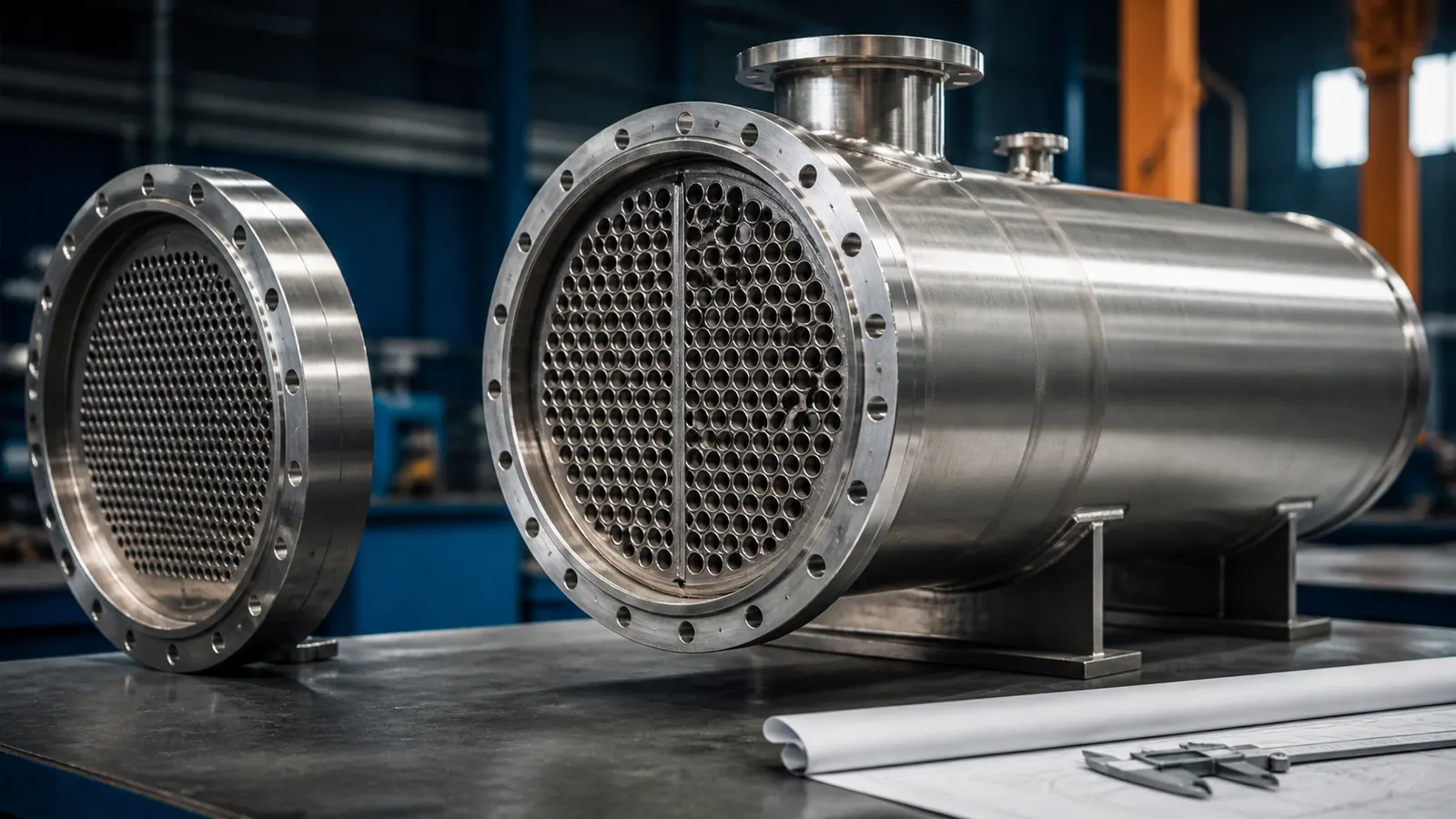
A heat exchanger transfers energy between fluid streams while keeping the required pressure boundaries and flow paths under control. In a shell-and-tube arrangement, thermal duty is delivered through a mechanical system of shell, tubes, tubesheets, baffles, channels, nozzles, supports and expansion provisions.
The selection process starts with process information: fluid properties, flow rates, inlet and outlet temperatures, allowable pressure drop, fouling behaviour and cleaning requirements. Mechanical and manufacturing review then turns that duty into a buildable arrangement with defined materials, connections, tube layout, access and inspection requirements.
This article explains product structure and the information needed for project review. It is not a substitute for project-specific thermal rating, vibration analysis, pressure design or code certification. Those activities must follow the approved engineering basis and the responsibilities agreed for the order.
Article Summary
- Define both fluid streams, thermal duty and allowable pressure drop before selecting the exchanger arrangement.
- Coordinate shell, tube bundle, tubesheets, baffles, channels, nozzles and expansion features as one assembly.
- Include cleaning, tube inspection, bundle removal and maintenance clearances in the design review.
- Keep illustrative thermal calculations separate from guaranteed project performance.
Heat Exchanger Structure and Design Inputs
The input package should identify which fluid is on the shell side and which is on the tube side, together with phase information, physical properties and fouling tendency. The selected allocation can affect material choice, pressure drop, cleaning and the arrangement of passes.
Site and maintenance information is equally important. A removable bundle requires extraction space. Channel covers and bonnets need lifting and access clearances. Nozzle loads, supports, insulation and connected piping affect the mechanical arrangement.
- Fluid names, composition, phase, flow rate and relevant physical properties for both sides.
- Inlet and outlet temperatures, thermal duty and any operating cases or turndown conditions.
- Operating and design pressure and temperature under the approved project basis.
- Allowable pressure drop, fouling basis, corrosion allowance and material requirements.
- Exchanger orientation, shell arrangement, number of passes and preferred maintenance concept.
- Tube outside diameter, wall, length, material, layout and tube-to-tubesheet joint basis where defined.
- Baffle type, spacing, cut or support arrangement and any vibration-review requirement.
- Nozzle sizes, ratings, orientation, projection and external interface requirements.
- Cleaning method, bundle removal space, inspection access and plugging or repair strategy.
- Applicable pressure-equipment, thermal-performance, material, welding, examination and documentation requirements.
Conceptual flow path: thermal duty, pressure drop, cleaning and mechanical structure are reviewed together.
Design Review Workflow
The workflow progresses from process data to exchanger selection, thermal review, mechanical arrangement and manufacturing handover.
- Validate fluid, flow, temperature, pressure-drop and fouling information for all required operating cases.
- Select the preliminary exchanger arrangement, fluid allocation, pass configuration and maintenance concept.
- Develop the thermal and hydraulic basis using the approved project method and responsibilities.
- Coordinate shell, tubes, tubesheets, baffles, channels, nozzles, supports and expansion provisions.
- Review fabrication access, tube-to-tubesheet work, inspection, cleaning, transport and installation.
- Release approved drawings, data sheets, inspection characteristics and documentation requirements.
Key Engineering Considerations
Fluid allocation and pass arrangement
The choice of shell-side and tube-side fluid influences velocity, pressure drop, cleaning and material exposure. A corrosive, high-pressure, fouling or difficult-to-clean stream may favour one side, but the complete process and mechanical context should be considered.
Pass arrangement changes velocity and temperature distribution. More passes can increase velocity and heat-transfer behaviour while also increasing pressure drop and channel complexity. The selected arrangement should be shown consistently on the data sheet, flow diagram and fabrication drawing.
Tube bundle and tubesheet
Tube outside diameter, wall, length, pitch and pattern affect available heat-transfer area, pressure drop, cleanability and tubesheet geometry. The tube-to-tubesheet joint may involve expansion, welding or a qualified combination depending on the project basis.
The design review should consider tube-hole tolerances, ligament geometry, tooling access and how joints will be inspected. Tube identification and material traceability should remain connected to the exchanger documentation.
Baffles, support and vibration considerations
Baffles direct shell-side flow and support the tubes. Their type, cut, spacing and clearances affect flow distribution, pressure drop and tube support. Inlet regions and unsupported spans may require additional review where vibration or erosion is a concern.
The webpage does not assign a universal baffle spacing or velocity limit. Those values depend on geometry, fluids, operating cases and the approved calculation method.
Thermal expansion and maintainability
Differences between shell and tube temperatures can create relative expansion. Fixed-tubesheet, U-tube, floating-head or expansion-joint arrangements manage that behaviour differently and also change cleaning and maintenance access.
A removable bundle needs clear extraction space and suitable lifting provisions. Even a non-removable arrangement requires practical access to channel covers, tube ends, plugs, drains and vents.
Pressure design and project responsibility
Heat exchangers may fall under pressure-equipment rules governing design, materials, fabrication, examination, testing, certification and marking. Thermal performance standards may also define rating or testing.
NOKX article content supports product understanding and manufacturing communication. Guaranteed duty, allowable loads, code calculations and certification are established only through approved project documents and responsible engineering parties.
Numerical Design Example
Illustrative logarithmic mean temperature difference
For a simplified counter-current example with terminal temperature differences of ΔT₁ = 40°C and ΔT₂ = 20°C:
LMTD = (ΔT₁ − ΔT₂) ÷ ln(ΔT₁/ΔT₂)
LMTD = (40 − 20) ÷ ln(40/20) ≈ 28.9°C
This value illustrates the temperature-driving-force calculation only. It does not determine required area, correction factor, heat-transfer coefficient, pressure drop, fouling allowance or guaranteed exchanger performance.
Materials and Applicable Standards
The project may combine thermal-performance, pressure-equipment, material, welding and customer requirements. The approved data sheet and drawings define the controlling basis.
| Review topic | Project design basis | Manufacturing handover |
|---|---|---|
| Process and thermal data | Validated fluids, flow rates, temperatures, duty, pressure drop and operating cases. | The released data sheet controls the selected configuration and performance review. |
| Mechanical basis | Approved pressure-equipment rules, materials, corrosion and load information. | Fabrication and inspection follow the approved mechanical design package where applicable. |
| Tube system | Tube material, OD, wall, length, pattern and joint basis. | Tube procurement, hole preparation, joining and inspection are coordinated. |
| Connections and access | Nozzle schedule, channel arrangement, drains, vents and maintenance clearances. | Machining, assembly, testing, preservation and lifting requirements are planned. |
| Documentation | Inspection plan, examination, testing and required records. | Project-specific records are linked to exchanger identification and revisions. |
Design Outputs and Manufacturing Handover
Typical outputs include a process data sheet, thermal-design basis where within the agreed scope, general arrangement, nozzle schedule, tube and tubesheet information, baffle layout, support details and inspection requirements. Every document should carry a controlled revision.
Manufacturing handover identifies materials, pressure-boundary welds, tube-to-tubesheet operations, sequence-sensitive dimensions, inspection access and test configuration. The drawing package should also identify which surfaces or interfaces require protection during packing.
Final documentation is agreed for the order. Material records, dimensional reports, welding and examination records, hydrostatic-test records and packing information are supplied when applicable to the product and inspection requirements.
Final dimensions, materials and manufacturing details are determined by approved drawings, applicable standards and project-specific requirements.
Frequently Asked Questions
Does the LMTD example size a heat exchanger?
No. It demonstrates one temperature relationship only. Exchanger sizing also requires fluid properties, heat-transfer coefficients, area, correction factors, fouling and pressure-drop review.
Which information is essential for an enquiry?
Provide both fluid streams, flow rates, temperatures, pressures, allowable pressure drop, fouling or cleaning basis, materials, preferred arrangement, quantity, applicable rules and documentation requirements.
Can tube layouts be customized?
Yes, subject to thermal, hydraulic, mechanical, manufacturing and maintenance review. The final layout must be shown on approved project documents.
How is thermal expansion considered?
The selected configuration must account for relative shell-and-tube expansion under approved operating cases. The solution may involve U-tubes, floating components, expansion provisions or another project-specific arrangement.
Will this page link to future exchanger products?
Yes. The Related Products area becomes clickable only after valid heat-exchanger tube or component pages are published.
Related Products
Discuss Your Heat Exchanger Design Requirements
Send your drawing, material, quantity and applicable standard for a project-specific technical review.