
DESIGN · TECHNICAL ARTICLE
Stainless Steel Prefabricated Assembly Design
A drawing-led approach to coordinating pipe sections, fittings, flanges, welds, supports and installation interfaces before stainless steel assemblies enter production.
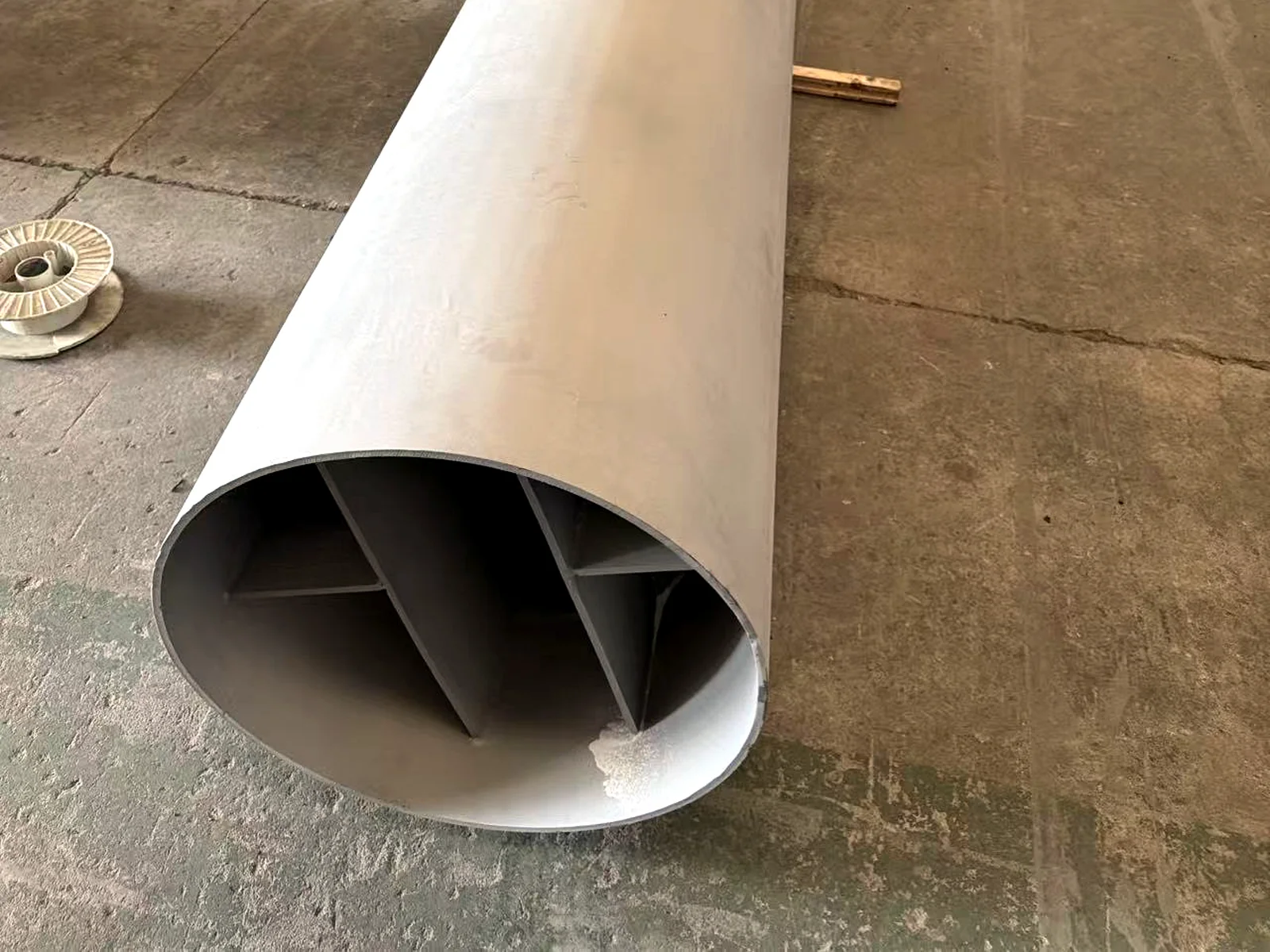
A prefabricated assembly combines several components into one controlled delivery unit. Straight pipe, elbows, tees, reducers, branches, flanges, supports and attachment plates may all be correct individually, yet the assembly can still fail to fit if datums, orientations and cumulative dimensions are not coordinated.
The design task is therefore spatial as well as dimensional. It converts a piping layout or equipment concept into a buildable assembly with defined coordinates, weld locations, inspection access, lifting points and transport limits. The drawing should enable production to reproduce the required geometry and enable the customer to verify the interfaces that matter at site.
For non-standard work, the approved assembly drawing becomes the main communication tool between customer, procurement, engineering, manufacturing and inspection. Component standards remain important, but they do not replace the need to define the relationship between those components.
Article Summary
- Use one assembly coordinate system and identify the primary installation datums.
- Control flange clocking, branch orientation, centreline coordinates and critical interface dimensions.
- Review weld access, examination access, transport segmentation, lifting and packing during design.
- Manage tolerance accumulation instead of applying the same tolerance independently to every dimension.
Assembly Structure and Project Inputs
The starting information should show where the assembly connects to the surrounding system. Equipment-nozzle coordinates, field-weld points, structural restraints and installation sequence can be more important than the length of any single pipe segment.
A useful input model includes both dimensions and function. The design team needs to know which interfaces are fixed, which can be adjusted at site and which dimensions are provided only for reference.
- Overall arrangement, process or piping layout and the required installation coordinate system.
- Connection-point coordinates, flange orientation, bolt-hole clocking and field-weld locations.
- Pipe and fitting dimensions, materials, wall thicknesses and applicable component standards.
- Branch angles, reducer orientation, drain direction and any required slope.
- Support, guide, anchor, lifting-lug and attachment requirements.
- Weld categories, access restrictions, examination scope and acceptance requirements.
- Transport envelope, maximum practical shipping section and site assembly sequence.
- Surface treatment, marking, documentation, preservation and export-packing requirements.
Assembly control: coordinates, datums and interface orientation govern fit-up across multiple components.
Design Review Workflow
The workflow establishes the assembly envelope first, then controls the component and weld details within it.
- Confirm equipment interfaces, site coordinates, field connections and installation constraints.
- Create a centreline and datum model that identifies fixed, adjustable and reference dimensions.
- Place components, branches, flanges, supports and welds with the required orientations.
- Review access for welding, dimensional inspection, NDT, cleaning, lifting and preservation.
- Divide the assembly into transportable sections where necessary and define site joints.
- Release the approved drawing, bill of materials, weld map and inspection characteristics to production.
Key Engineering Considerations
Datums, coordinates and flange clocking
A primary datum should be a stable interface that production and site teams can identify, such as a flange face, pipe centreline intersection or machined mounting surface. Secondary datums control rotation and height. If each dimension is taken from a different informal reference, the assembly may be impossible to inspect consistently.
Flange clocking requires a reference axis. The drawing should state whether a bolt hole or the gap between holes aligns with that axis. On a multi-flange assembly, the relative orientation between flanges should be controlled even when each individual flange meets its own bolt-pattern dimensions.
Tolerance accumulation
An assembly contains many dimensional contributors: cut lengths, fitting centre-to-end dimensions, weld gaps, weld shrinkage, flange thickness and measurement uncertainty. Applying a tight tolerance to every local length is not always the best solution. The design should identify the final interfaces that matter and allocate control to them.
Where possible, critical coordinates are dimensioned from a common datum instead of through a long chain of dimensions. Fit-up and final dimensional checks can then focus on the installation points rather than attempting to infer them from accumulated local measurements.
Weld layout and inspection access
Weld position affects both production and verification. A weld placed too close to a branch, support or flange may restrict torch access, examination scanning or repair. The drawing review should also consider internal access for cleaning and whether the assembly can be drained after testing.
A weld map can assign a unique identity to each joint and connect it to the welding and inspection records. This is especially useful when the assembly contains different wall thicknesses, materials or examination requirements.
Transport, lifting and site completion
A shop-fabricated assembly must still pass through doors, lifting routes and transport frames. Overall dimensions, centre of gravity, temporary supports and lifting points should be reviewed before the assembly is frozen. Shipping sections should protect precision interfaces and provide practical field joints.
Temporary braces and covers should be identified as such. Their removal instructions, lifting restrictions and protected surfaces can be included in the drawing or packing documentation so that site teams do not mistake temporary items for permanent components.
Numerical Design Example
Three linked dimensions with ±2 mm tolerances
Assume three serial dimensions are each independently specified as ±2 mm. A simple worst-case stack is:
±2 + ±2 + ±2 = ±6 mm
The ±6 mm result does not mean the assembly will always deviate by that amount. It shows the maximum arithmetic accumulation if all three contributors move in the same direction. If the final interface requires tighter control, the drawing can dimension that interface directly from a common datum, use an adjustable fit-up location, or assign a tighter tolerance only to the dominant contributors.
The example illustrates why assembly drawings need a tolerance strategy rather than a collection of unrelated local tolerances.
Materials and Applicable Standards
The assembly design draws together component, material, welding and inspection documents. The approved assembly drawing resolves how those requirements interact.
| Review topic | Project design basis | Manufacturing handover |
|---|---|---|
| Component basis | Pipe, fittings, flanges and attachments are identified by drawing or applicable product standard. | Incoming and in-process checks confirm the selected components before assembly. |
| Coordinate control | Datums, centreline coordinates, slopes and orientations are defined on the assembly drawing. | Fit-up and final inspection use the same datum system. |
| Welding | Joint details, materials, access and applicable welding requirements are reviewed. | A weld map and routing connect joints with production and examination records. |
| Dimensional acceptance | Critical interface coordinates, flange alignment and overall envelope are identified. | Final dimensional reports focus on installation-critical characteristics. |
| Packing and delivery | Shipping sections, lifting, temporary supports and protected faces are defined. | Packing preserves geometry and identifies site joints and removable items. |
Design Outputs and Manufacturing Handover
A complete design output may include the general arrangement, fabrication drawings, bill of materials, component schedule, weld map, datum scheme, inspection characteristics and packing or lifting notes. The level of detail depends on project complexity, but every critical interface should be visible without relying on verbal instructions.
Production handover begins with a drawing review involving fabrication, welding and inspection personnel. This review identifies sequence-sensitive work, access limitations, temporary fixtures and measurements that should be recorded before later components obstruct them.
Final documentation can link material identity, weld records, examination results and dimensional reports to the assembly identification. The exact document package is agreed for the order rather than assumed to be identical for every assembly.
Final dimensions, materials and manufacturing details are determined by approved drawings, applicable standards and project-specific requirements.
Frequently Asked Questions
What information is needed to quote a prefabricated assembly?
Provide the arrangement or model, connection coordinates, components, materials, wall thicknesses, standards, weld and inspection requirements, quantity, transport limits and required documentation.
How are flange orientations controlled?
Use a stated datum and define whether a bolt hole or the space between holes aligns with the reference axis. Relative clocking between multiple flanges should also be dimensioned.
Can the assembly be divided for transport?
Yes, when the design identifies suitable shipping sections, protected interfaces, temporary supports and practical field joints. The final split requires project approval.
Why are common datums important?
They prevent tolerance chains from obscuring the final installation coordinates and allow production and inspection to measure from the same references.
Can related product pages be linked later?
Yes. The Related Products area remains inactive until the relevant pipes, fittings or assemblies are published, then becomes a valid product-entry area without creating dead links.
Related Products
Discuss Your Prefabricated Assembly Design Requirements
Send your drawing, material, quantity and applicable standard for a project-specific technical review.